Coding prevents incorrect plugging of connectors
Coding is used to avoid incorrect accidental mating of similar connectors. Essentially, there are three different techniques:
- Visual markings such as printed symbols, notches, colour clips and labels on the connector make it easy for the user to find the correct orientation
- Accessories such as guide pins and bushes, coding pins or shells physically prevent improper couplings.
- In the field of circular connectors, standardised mating faces such as A-, B-, D- or X-coding also prevent errors when plugging.
Coding options for Han® industrial connectors
Coding pins
Two out of four fixing screws for an insert within a hood or housing can be replaced by coding pins. If the connectors are mated incorrectly, the coding pins collide and prevent further insertion. Each coding pin on one side of the connector must face a fixing screw on the other.
Guide pins / bushes
In this type of coding, guide pins / bushes replace the fixing screws in the connector inserts or frames. The pins allow mating alignment at an angle of up to ± 5° in the longitudinal direction and ± 2° in the transverse direction. Increased inclinations are prevented. The guide pins and bushes serve as coding elements; mating only works, if the complementary pairs match correctly. Considering the maximum of four guide pins or bushes per application, there are 16 different coding options in total.
Other coding elements
Alternatively, plastic pins and bushes can be used (in the Han® series, standing out by their red colour). Each of them is capable of replacing crimp contacts of the Han® C, Han® D, DD; Han E®, Han® EE and Han® EEE series. For most contact inserts, however, this method means that one contact position is lost for the coding. The situation is different with Han® Q and Han-Yellock®, which are equipped with separate cavities for the coding. Han® Q5 for example contains two cavities, each offering six positions for coding pins or bushes, adding up to 36 coding options.
Coding for devices and PCB connectors
One must differentiate between …
- Coding that designates a mating face according to a standard, e.g., for circular connectors M8, M12 and M23
- Additional coding elements (often coloured) such as coding clips or coding rings and pins or keys, fins, recesses, bars, flange or collar coding, which form a physical barrier to mating
Coding of PushPull connectors
In order to prevent incorrect insertions of connectors with PushPull locking, for example RJ45 interfaces, accessories like coloured clips can be placed on the hood or housing.
Circular connectors M8, M12 and M23 Circular connectors are used for installing machines and systems as well as for device connectivity. They are designated according to their thread dimensions as M8, M12, M23 or 7/8 inch. Certain arrangements of contacts are standardised and used e.g. referred to as A, B, D, and L or X coding. If several circular connectors of the same coding are used side by side, security against confusion can be produced by different snap-in options for the insulating bodies in the housing.
M8 connectors
- 3- or 4-pole, A-coding
M12 connector
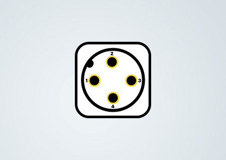
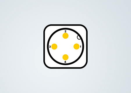
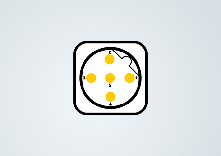
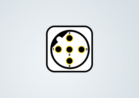
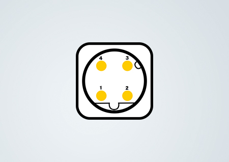
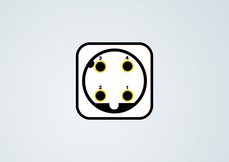
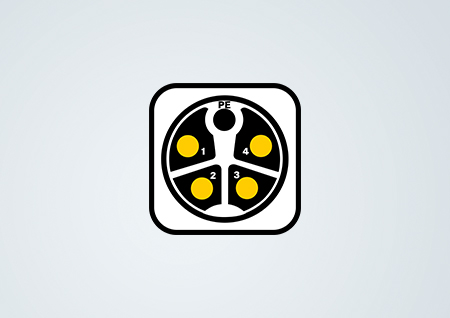
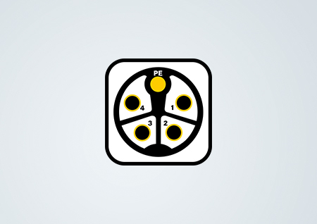
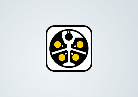
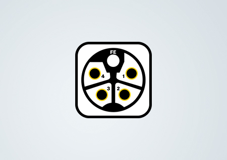
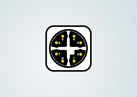
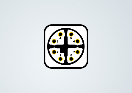
M12 connectors are available in versions from three up to twelve poles. Depending on the version, the coding options are A, B, D, X or Y. Thus, the correct mating position is clearly defined by the geometry of the insert and the arrangement of pins and bushes. To avoid confusion and incorrect mating, different codings are used for connectors with the same or similar function.
M23
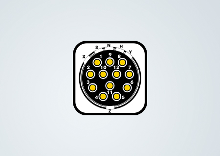
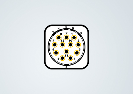
The M23 Signal circular connector is equipped with an arrangement of up to 19 contacts. Coding is realised by fitting a fin in the housing to a recess in the insulation body. Therefore, the insulation bodies of the HARTING portfolio offer six optional rotary positions – X, H, N, S, Y, Z (refer to drawing). Consequently, up to six M23 signal connectors with identical mating faces can be assembled side by side without any risk of confusion.
DIN connectors
Connectors for PCB contacting according to DIN 41 612 are coded on both sides of the plug connection. A maximum of 12 pins can be snapped into coding bars on the sides of each connector. This leads to over 900 different coding options. The relevant bars can be screwed, welded or moulded to the connectors. As an advantage, the coding via the bars does not use contact positions. In addition, there are also methods where a contact in the female DIN connector is replaced by a coding pin. The corresponding male contact must then be removed in the mating position with a tool (=>HARTING Catalogue, DIN 41 612, Coding, p. 00 · 14).

